
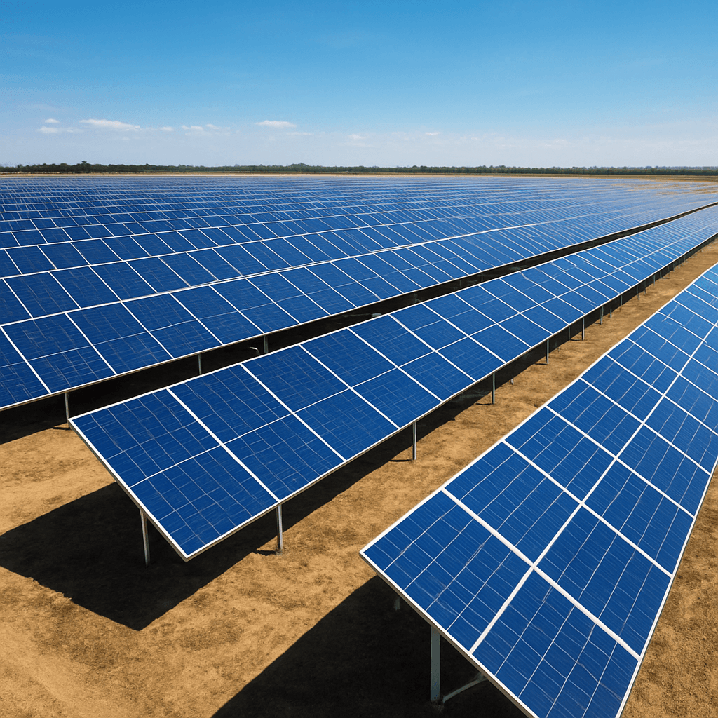
Ground-Mounted Solar Projects Start with Site and Foundation Conditions
The upper structure is only one part of a ground-mounted PV project. Soil condition, foundation direction, site layout, corrosion environment and load requirements all influence the mounting specification.
The Site Determines the Foundation Direction.
Ground-mounted PV installations face varied site topography, soil bearing capacities, wind uplift forces, and atmospheric exposure. Selecting the structural racking and foundation method based on thorough site evaluation ensures long-term structural integrity and efficient field deployment.
Ground Project Decision Sequence
Site Condition
Review soil parameters, terrain slope, corrosion class, and site access.
Foundation Direction
Evaluate ground screw, C/H driven pile, or concrete foundation options.
Mounting Structure
Select aluminum or hot-dip galvanized steel racking geometry and spans.
Module Layout
Define table configuration (N×P or N×L), tilt angle, and ground clearance.
Accessory & Delivery
Confirm grounding hardware, cable clips, and containerized packing schedule.
Ground Project Input Matrix
How site parameters directly shape structural design and procurement.
| Project Input | What It Influences |
|---|---|
| Soil / Ground Information | Foundation method selection (ground screw embedment length, driven pile depth, or concrete ballast) |
| Site Layout & Terrain Slope | Structure arrangement, row spacing, east-west or north-south slope adaptation, and table lengths |
| Module Dimensions & Type | Table configuration (e.g. 2×20 portrait or 4×10 landscape), purlin spacing, and clamp selection |
| Tilt Angle | Structural geometry, front/rear leg height, wind uplift profile, and shading clearance |
| Wind & Snow Requirements | Steel profile thickness, purlin section modulus, bracing frequency, and fastener grade |
| Corrosion Environment | Material choice (aluminum AL6005-T5 vs hot-dip galvanized steel Q235B/Q355B coating thickness) |
| Foundation Preference | Ground screw flange type, pile profile, or cast-in anchor bolt template requirements |
| Project Schedule & Logistics | Phased supply coordination, bundle packaging, container loading density, and delivery sequencing |
Evaluating Foundation Options at Project Stage
Foundation direction depends on site and project requirements. Ground screws offer fast installation in sandy, clay, or rocky soils with immediate load-bearing capacity. Driven C/H steel piles perform well in uniform soft soils for large-scale utility arrays. Concrete pad foundations are preferred for hard rock, contaminated land, or sites where ground penetration is prohibited. Final foundation choice should align with site soil conditions and installation machinery access.
Ground Project Risks Often Begin Before the Structure Is Quoted
Key pitfalls that lead to budget overruns and field rework on ground PV installations.
Quoting from MW capacity only
Estimating ground racking purely on total megawatt size without module dimensions or table layouts leads to incorrect steel tonnage and purlin quantities.
Foundation assumed without soil information
Selecting driven piles or ground screws without reviewing soil conditions risks pile refusal in rocky ground or insufficient pull-out capacity in loose soil.
Different suppliers using different BOM scopes
Comparing quotes where one supplier omits diagonal bracing, purlin splices, or grounding hardware creates unexpected field purchasing costs.
Material assumptions not aligned
Failing to specify hot-dip galvanizing coating thickness (e.g. 55μm vs 80μm) or aluminum alloy temper results in mismatched corrosion resistance.
Corrosion environment ignored
Deploying standard structural steel near coastal or high-salinity zones without heavy galvanizing or specialized coatings accelerates rust formation.
Transport volume discussed too late
Ground racking involves high volumetric weight. Neglecting container packing density during design increases shipping freight overhead.
Project Information to Prepare for Ground Mount RFQ
Essential site data required to design and quote a ground-mounted solar racking system.
Relevant Product Categories
Explore the mounting systems and hardware accessories matched to this solution type.
Relevant Product Categories for Ground Projects
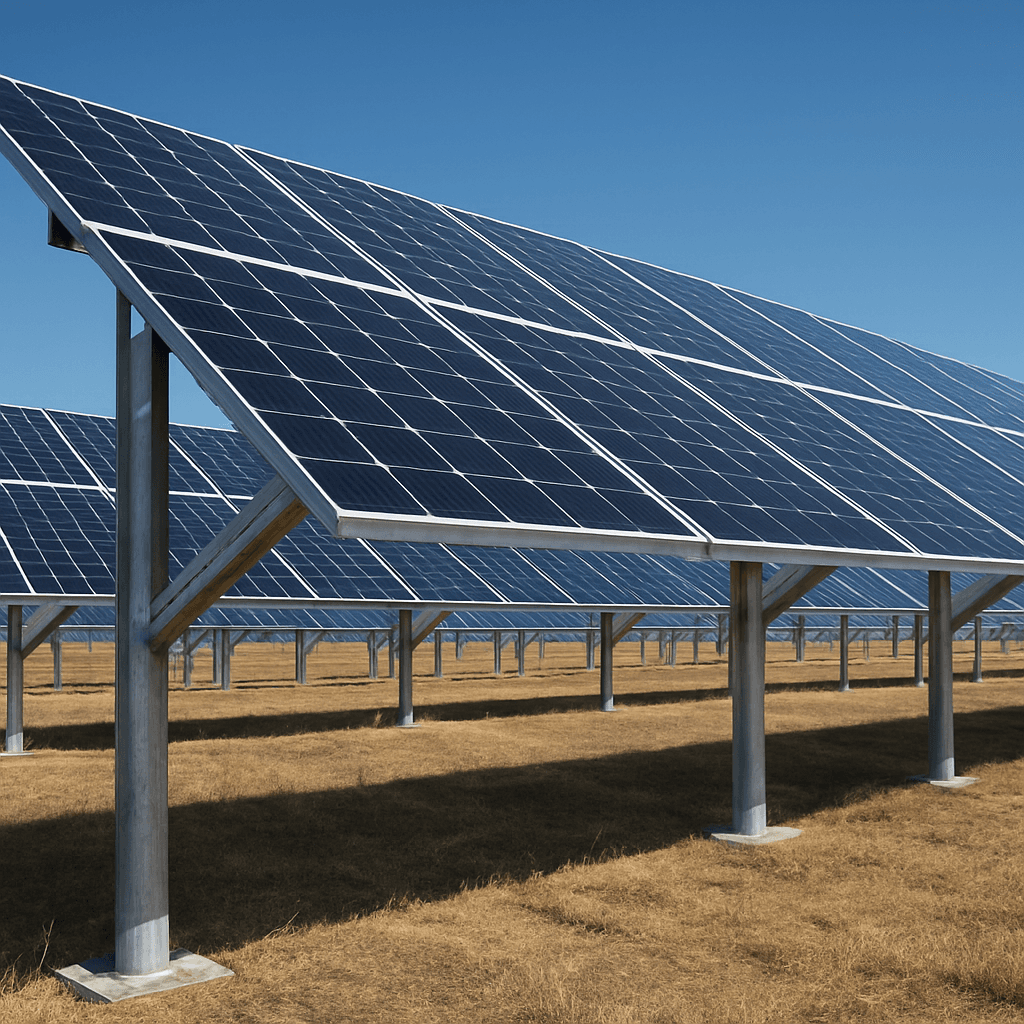
Ground Solar Mounting Systems
Aluminum, pile and galvanized steel ground mounting options for commercial and utility PV projects, selected according to soil condition, foundation method and project layout.
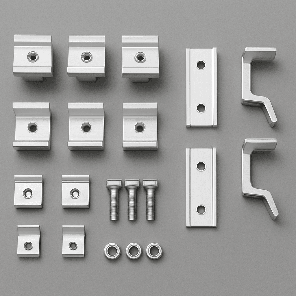
Solar Mounting Accessories
Rails, mid clamps, end clamps, roof hooks, grounding clips, cable clips, bolts and fasteners for roof and ground PV installation.
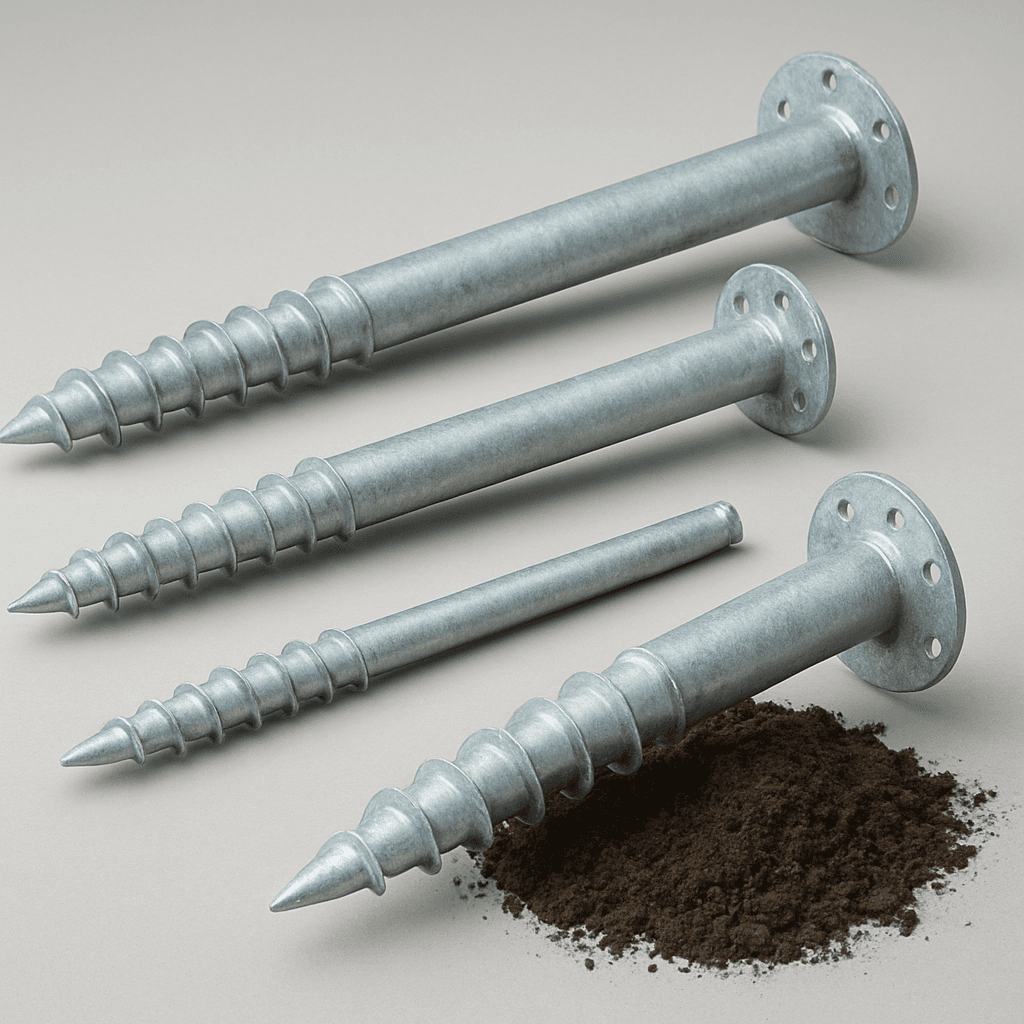
Ground Screws
Galvanized ground screw foundation products for ground solar mounting systems, selected according to soil condition, diameter, length and pull-out requirements.
FAQ
Frequently Asked Questions
Define the Ground Project First
Provide your site layout, soil conditions, and module specs to receive a tailored ground mounting structural proposal.