
Ground Solar Mounting Systems Built Around Site Conditions
Ground mounting selection starts below the structure. Soil condition, foundation method, layout, load requirements, corrosion environment and installation method all affect the final mounting configuration.
XINVOK supports aluminum, pile and galvanized steel ground mounting supply according to confirmed project conditions.
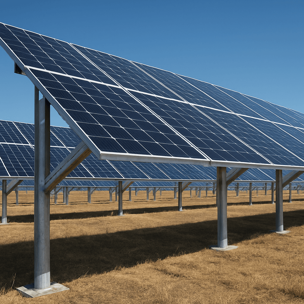
FOUNDATION LOGIC
The Foundation Defines the Ground Structure.
A ground mounting system cannot be specified from module quantity alone.
The foundation must respond to site conditions before the upper structure is finalized.
Ground screws, driven piles and concrete foundations each create different structural and installation requirements.
Foundation Comparison
| Foundation Direction | Project Information Needed | Typical Consideration |
|---|---|---|
| Ground Screw | Soil information, screw dimensions, installation requirement | Installation speed and soil compatibility |
| Driven Pile | Soil condition, pile requirement, structural layout | Equipment access and foundation design |
| Concrete Foundation | Foundation design, site preparation, structure interface | Civil work and project schedule |
Structure Material Direction
Ground mounting structures are supplied in aluminum, hot-dip galvanized steel, and pile-supported configurations. Material choice depends on structure design, environmental exposure, project scale, site handling, corrosion considerations, transport volume, and project requirements. No single material is universally superior for every ground site.
Key System Features
Multiple Foundations
Driven pile, ground screw or concrete foundation options to suit soil condition.
Adjustable Tilt
Fixed-tilt structures set to optimal angle for project latitude and yield target.
Galvanized Steel
Hot-dip galvanized steel members for strength and corrosion resistance on open sites.
Scalable Layout
Modular spans designed for fast assembly across large utility and commercial arrays.
QUOTATION PREPARATION
What to Confirm Before Quotation
Providing site and foundation parameters upfront enables an accurate structural quotation.
PROCUREMENT RISK MITIGATION
Ground Mounting Risks That Usually Appear Too Late
Avoid these common ground project sourcing pitfalls during procurement.
Foundation selected before soil condition is understood
Choosing ground screws or piles without checking soil strata leads to drive-in resistance or insufficient pull-out capacity.
Quoting from MW capacity alone
MW capacity does not define racking layout. Array table arrangement, module dimensions, and slope alter steel and rail requirements.
Ignoring corrosion environment
High-salinity or acidic soil requires heavier hot-dip galvanizing or specialized coatings to prevent premature corrosion.
Missing foundation components from the quotation
Leaving foundation bolts, pile caps, or ground screw flange adapters out of the BOM creates unexpected field procurement costs.
Different suppliers quoting different BOM scopes
Comparing quotes without aligning hardware scope (purlins, bracing, fasteners, grounding) leads to misleading price evaluations.
Transport volume not considered until shipment
Bulky structural purlins and columns impact container loading density. Logistics planning must occur during design.
Specifications
| Materials | Material options can be confirmed according to project requirements. |
|---|---|
| Foundation | Driven pile, ground screw or concrete options. |
| Tilt angle | Set according to project layout and yield target. |
| Modules per table | Custom according to layout. |
| Wind & snow load | Wind and snow load requirements are reviewed according to project conditions. |
| Coating & fasteners | Fastener and coating options can be discussed according to installation environment. |
Specifications are indicative and confirmed per project. Send your requirement for exact values.
Typical Applications
- Utility-scale solar farms
- Commercial ground arrays
- Agricultural PV
- Open-field projects
Engineering & Solution Resources
FAQ
Frequently Asked Questions
Related Products
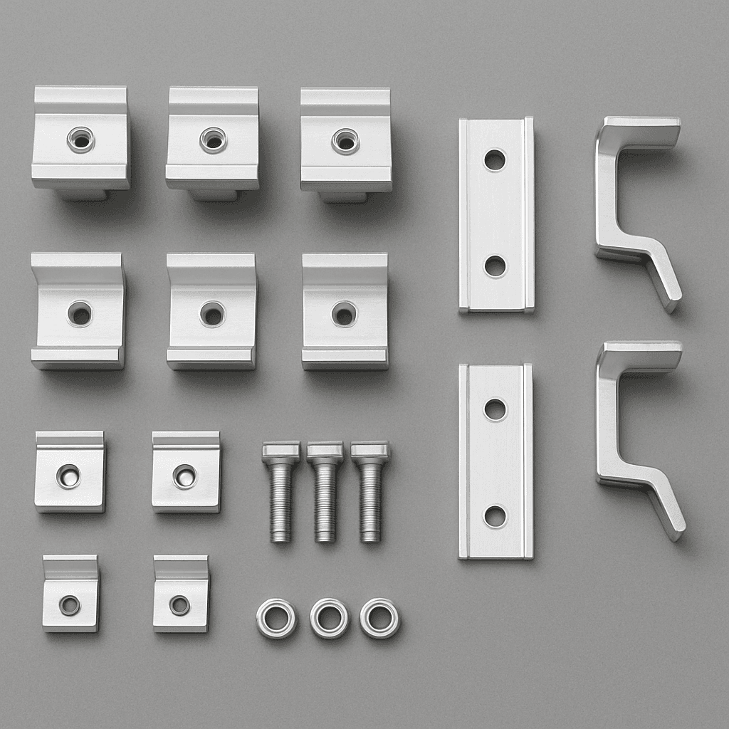
Solar Mounting Accessories
Rails, mid clamps, end clamps, roof hooks, grounding clips, cable clips, bolts and fasteners for roof and ground PV installation.
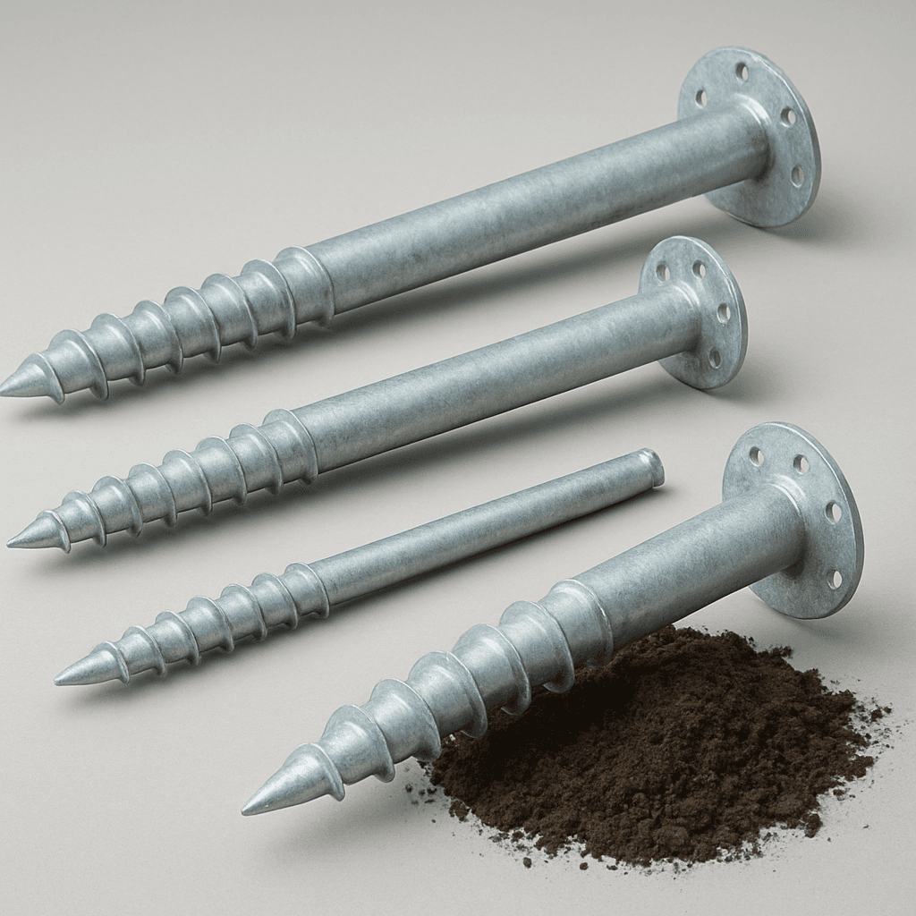
Ground Screws
Galvanized ground screw foundation products for ground solar mounting systems, selected according to soil condition, diameter, length and pull-out requirements.
Project Quotation
Prepare Your Ground Project Details
Send soil conditions, module layout, foundation preference and available project requirements. XINVOK will assist in reviewing structure options and quotation requirements.