
Solar Mounting Solutions Built Around Project Conditions
Solar mounting requirements change with the project environment. Roof interface, site condition, parking geometry, project scale and site perimeter can all change the structure, accessory list and supply scope.
XINVOK organizes mounting solutions around the conditions that shape the project before quotation begins.
Different Project Conditions Create Different Mounting Decisions.
Select your project category to review the specific site variables, decision matrix, risk factors, and checklist required before quotation.
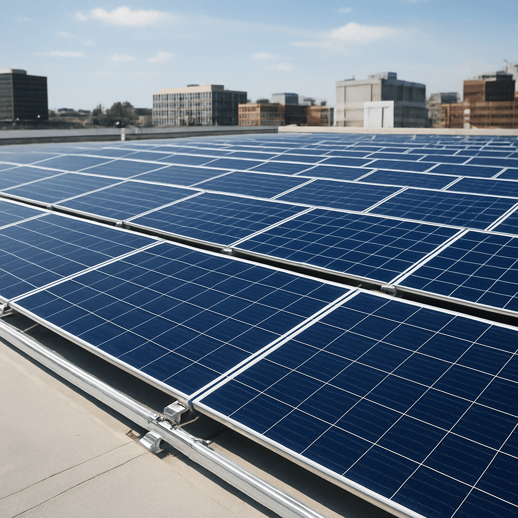 Pathway 01
Rooftop Solar Mounting
For residential, commercial, and industrial rooftop installations across standing seam, trapezoidal, tile, flat concrete, and asphalt shingle roofs.
Key Decision Principle
“The roof interface determines attachment, waterproofing and accessory selection.”
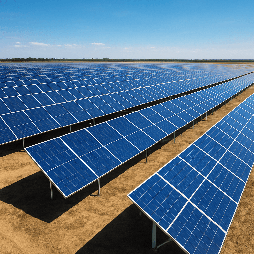 Pathway 02
Ground-Mounted Solar Projects
For commercial and utility-scale solar arrays requiring aluminum alloy or hot-dip galvanized steel structures with adaptable foundation methods.
Key Decision Principle
“Soil, foundation method and site conditions shape the ground structure.”
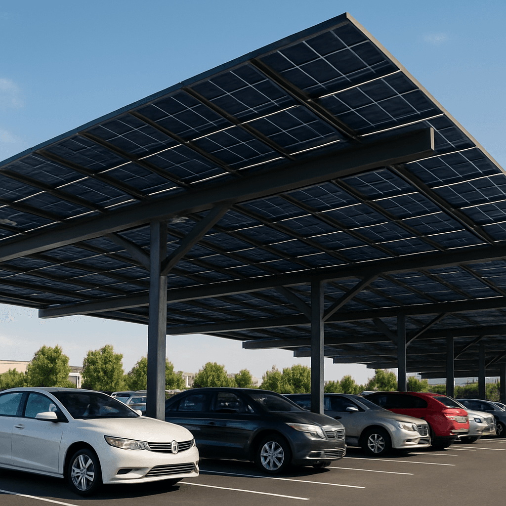 Pathway 03
Solar Carport Projects
For commercial parking lots, public garages, and corporate campuses combining PV power generation with vehicle shade and drainage.
Key Decision Principle
“Parking layout, span, clearance and drainage define the carport configuration.”
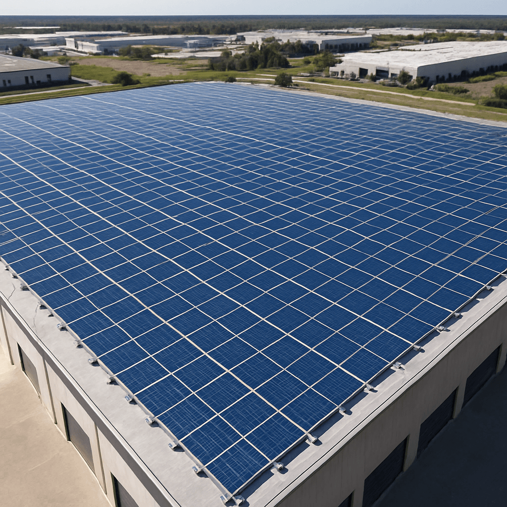 Pathway 04
Commercial Solar Mounting
For multi-building factory complexes, logistics parks, and multi-zone developments requiring specification control and phased supply.
Key Decision Principle
“Commercial projects require consistent specifications, BOM control and coordinated supply across larger project scopes.”
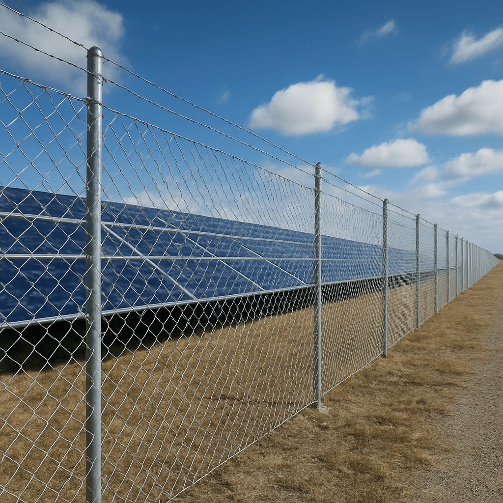 Pathway 05
Solar Farm Site Protection
For solar farm physical security, perimeter fencing, corner bracing, gate access points, and durable corrosion protection.
Key Decision Principle
“Perimeter, access, terrain and gate requirements define the site protection scope.”
From Project Condition to Supply Scope
A structured 4-step framework ensures site conditions are translated into complete, actionable mounting system packages without field gaps.
Define the Application
Establish whether the installation site is a rooftop, open ground array, parking lot, multi-zone commercial complex, or farm perimeter.
Clarify Site Conditions
Evaluate roof profiles, soil parameters, parking geometry, wind/snow design loads, and corrosion environment requirements.
Match Products and Accessories
Select specific rail profiles, foundation anchors, mid/end clamps, fasteners, and grounding accessories as a complete system.
Prepare Supply Scope
Organize itemized BOMs, drawing revisions, kit packing, and container shipping schedules matching construction milestones.
Need Engineering Review or Layout Support?
Explore structural calculation guidelines, wind/snow load input formats, and drawing support.